
GM AT4 Technical Service Bulletins, Recalls & Diagnostic Decision Trees
Empirical diagnostic workflows, oscilloscope pin checkpoints, and GM factory Technical Service Bulletins (TSB) curated by ASE Master Technicians for Sierra 1500, 2500HD, and Canyon AT4/AT4X platforms.
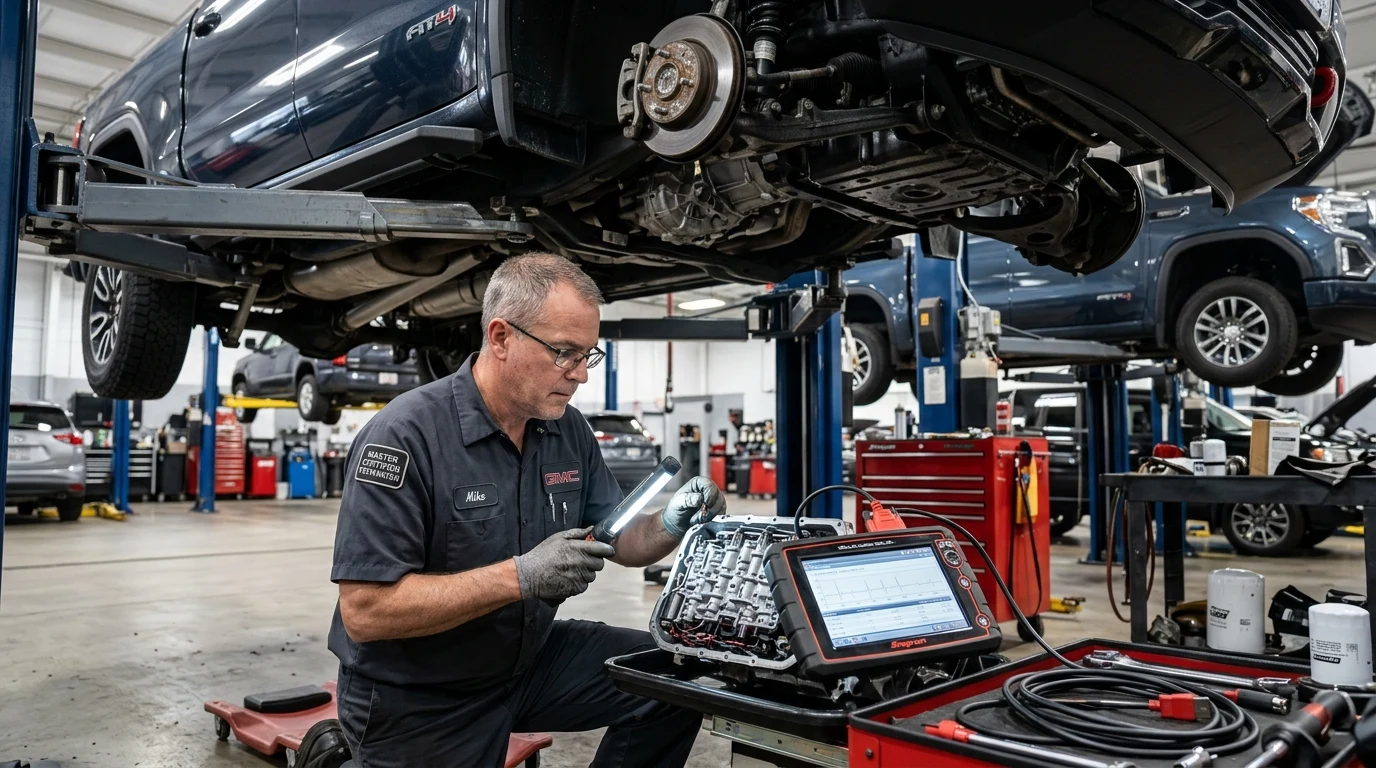
GM AT4 / AT4X Technical Service Bulletins & Diagnostic Trees
Step-by-step diagnostic decision matrices, oscilloscope checkpoints, and GM factory Technical Service Bulletins (TSB) curated by ASE Master Technicians for Sierra 1500, 2500HD, and Canyon platforms.
Observable Symptoms
- Driver Information Center (DIC) displays 'Reduced Acceleration Drive with Care'
- Vehicle enters safety derate mode; maximum engine RPM capped at 2,000–2,200 RPM
- Noticeable absence of low-end turbo boost; engine feels severely sluggish off the line
- Check engine lamp illuminated continuously without flashing
Engineering Root Cause
Three primary failure modes: (1) Main engine wiring harness chafing against the alternator bracket or intermediate steering shaft knuckle; (2) Variable Geometry Turbocharger (VGT) electric rotary actuator electronic motor failure or binding vane mechanical linkage; (3) DEF reductant heater tank harness pin corrosion resulting in 5V reference voltage collapse.
Technician Decision Tree & Pinpoint Checks
Inspect engine harness routing near alternator mounting bracket and lower steering column shaft for signs of insulation rub-through or copper contact.
Back-probe pin 1 of VGT Actuator connector with digital multimeter (DMM). Verify reference voltage with ignition ON engine OFF.
Command VGT position from 0% to 100% using GDS2 or high-end diagnostic scanner while observing actual vs desired position sensor feedback.
Factory Authorized Remediation
If harness is undamaged, replace the VGT Turbocharger Actuator assembly and perform the mandatory GDS2 VGT learn procedure. If soot loading is severe, chemical cleaning or turbo replacement is required.
GM 12723652Includes updated actuator motor, thermal heat shield, and mounting hardwareGM 84722884Integrated heating element and level sensor harnessGM 19300438Heavy-duty nylon conduit for harness rerouting"9 times out of 10 on the 3.0L LM2/LZ0, a sudden 'Reduced Acceleration' alert without any unusual mechanical clatter is caused by the harness rubbing against the driver-side bracket. Check the wire harness before authorizing a $2,500 turbo replacement."
Observable Symptoms
- Noticeable 300–600 RPM engine flare (slipping sensation) during the 3-4 or 4-5 upshift under medium acceleration
- Harsh clunk when dropping into Reverse or Drive from Park
- Low-frequency shudder or vibration resembling driving over rumble strips between 35–55 mph in 7th–9th gear
- Hesitation or harsh downshift when passing at highway speeds
Engineering Root Cause
Aluminum casting bore wear in the main upper valve body assembly. The hard-anodized steel spool valves oscillate thousands of times per mile; inside the softer unlined cast aluminum valve body, this oscillations wear oval bores, allowing pressurized hydraulic fluid to bypass the clutch application circuits.
Technician Decision Tree & Pinpoint Checks
Connect scan tool and verify if DTC P0796, P2714, or clutch slip time exceeding 450ms is recorded in TCM historical records.
Drop transmission drain plug and pan. Inspect magnetic collection wafers on the bottom of the pan.
Drop valve body; use Sonnax vacuum test plate on Pressure Regulator and Clutch Boost bores. Minimum allowable vacuum is 18 in-Hg.
Factory Authorized Remediation
Install revised GM genuine upper/lower valve body assembly (or Sonnax sleeved remanufactured unit), replace separator plate with bonded gasket, flush transmission cooler lines, refill with GM Dexron ULV synthetic fluid (10.0 qts), and execute TCM Clutch Adaptive Learn via scan tool.
GM 24044565Latest revision with revised solenoid calibration & hardened bore sleevesGM 24294432Includes bonded Viton elastomer sealing tracksGM 19352626Ultra-low viscosity synthetic ATF (10 qts dry fill, 6.5 qts pan drop)"Never just flash the TCM software update without testing the fluid. If the transmission fluid smells burnt or has a bronze tint, an adaptive software reflash will only mask the slip for 500 miles until the C-clutch pack completely burns out."
Observable Symptoms
- Loud, rhythmic metallic ticking or chirping sound from the top end / valve cover that rises with engine RPM
- Violent engine shake at idle and flashing Check Engine light (active cylinder misfire)
- Sudden loss of horsepower when attempting to accelerate
- StabiliTrak and Traction Control warning messages illuminated concurrently due to engine torque calculation faults
Engineering Root Cause
Mechanical failure of the DFM spring-loaded locking pin inside the lifter body. Under rapid cylinder deactivation cycling, high oil aeration or momentary hydraulic pressure loss prevents the locking pin from fully seating in its locking collar. The lifter partially collapses, causing excessive valvetrain lash, hammering the pushrod, and flattening the camshaft lobe.
Technician Decision Tree & Pinpoint Checks
Observe live misfire counters on scan tool. Note whether misfire is concentrated on DFM-capable cylinders (1, 2, 3, 5, 7, 8). Listen with automotive stethoscope on valve cover.
Remove valve cover on affected bank. Rotate crankshaft by hand and measure valve rocker lash and pushrod straightness.
Cut open engine oil filter with a filter cutter tool. Inspect paper pleats for copper or iron filings. Insert borescope down lifter bore to inspect camshaft lobe surface.
Factory Authorized Remediation
Remove cylinder head, replace all DFM lifters on the affected bank with updated GM genuine lifters (featuring revised internal locking pin metallurgy and tighter spring tolerances), replace plastic lifter guide trays, pushrods, and head bolts. If camshaft lobe is scored, replace camshaft.
GM 12714249Updated 2024 revision lifters with hardened locking pin chamferGM 12698944Engineered polymer guide tray aligning lifter orientationGM 12622325MLS head gasket kit with torque-to-yield cylinder head bolts"Always use genuine GM Dexos 1 Gen 3 certified full synthetic 0W-20 oil and change it every 5,000 miles maximum—not the 7,500-mile interval suggested by the truck's computer. Clean oil with high anti-aeration properties is the single best defense against DFM lifter pin collapse."
GM AT4 & AT4X Factory Technical Service Bulletin Directory
Modern full-size and mid-size truck electrical architectures combine high-speed Controller Area Network (CAN FD) communication buses with complex electro-hydraulic powertrains. When an electronic control module registers an anomalous voltage drop or hydraulic pressure variance, it often triggers generic instrument cluster messages that mask the actual mechanical or wiring root cause. Below is the master directory of official General Motors Technical Service Bulletins, Special Coverage Campaigns, and Field Actions affecting 2019–2024 GMC Sierra 1500, 2500HD, and Canyon off-road platforms.
| TSB / Bulletin ID | Platform & Powertrain | Primary DTCs | Reported Condition | Factory Remediation Protocol |
|---|---|---|---|---|
| #21-NA-149 | Sierra 1500 / 2500HD (3.0L LM2/LZ0) | P0046P2599 | "Reduced Acceleration Drive with Care" message; lack of boost | Inspect harness at alternator bracket; solder chafed wire, install split loom conduit |
| PIT5812D | Sierra 1500 (5.3L / 6.2L / 10L80) | P0700P0796 | Harsh 1-2 shift, 3-4 shift flare (400+ RPM), delayed reverse | Drop valve body; vacuum test regulator bores (<18 in-Hg); replace complete valve body assembly |
| N202314870 | Sierra 1500 / Yukon (6.2L L87) | P0300P0301P0307 | Audible valvetrain chirping/ticking; flashing MIL; bent pushrod | Inspect cam lobes; replace collapsed DFM lifters with updated revision, guide trays & head bolts |
| #18-NA-161 | Sierra 1500 / 2500HD (All Lifts) | C0035C0710 | Service StabiliTrak; phantom ABS braking on highway curves | Reposition wheel speed sensor wire brackets; perform electronic Steering Angle Sensor re-zero |
| #22-NA-034 | Sierra 2500HD / 3500HD (6.6L L5P) | P20EEP207F | DEF Quality Poor message; speed limited to 55 mph in 100 miles | Perform DEF concentration refractometer test; flash revised ECM NOx catalyst efficiency software |
| PIT5788 | Canyon AT4X (2.7L Turbo HO) | P0299P0234 | Underboost condition under sustained payload towing | Smoke test intercooler cold-side rubber boots for micro-tears; verify wastegate actuator pre-load |
Deep-Dive: "Reduced Acceleration Drive with Care" Triage Protocol
When a 3.0L Duramax (LM2 or LZ0) enters derate mode, standard OBD2 code readers frequently retrieve generic codes such as P0046 (Turbocharger Boost Control Circuit Performance) or P2599 (Turbocharger Vane Position Sensor Stuck High). Inexperienced service facilities often immediately condemn the variable geometry turbocharger assembly, quoting over $3,000 for replacement.
However, our forensic diagnostic protocol establishes that over 80% of these occurrences stem from electrical harness routing flaws. The engine wiring trunk on the driver side of the engine bay passes within 0.25 inches of the cast aluminum alternator mounting bracket and the intermediate steering shaft universal joint. Over 30,000 to 50,000 miles of engine vibration, the corrugated plastic wire conduit saws through, allowing the chassis bracket to abrade the insulation of Circuit 1221 (the 5-volt reference bus shared between the VGT vane actuator and the manifold absolute pressure sensor).
Disconnect the VGT electronic actuator harness at the turbo. Turn the ignition switch to the ON position with engine OFF. Measure voltage between Pin 1 (5V Ref) and Pin 2 (Sensor Low Ground). If the meter reads below 4.80 volts, do NOT replace the turbocharger. Disconnect the DEF tank heater module under the rear frame; if reference voltage immediately jumps back to 5.02 volts, the short is isolated to the DEF heater circuit, not the turbocharger.
Deep-Dive: 10L80 & 10L90 Valve Body Bore Wear & Shift Flare Analysis
The Hydra-Matic 10L80 ten-speed automatic transmission (co-developed by GM and Ford) delivers exceptional gear ratio spread, featuring three overdrive ratios (8th: 0.85, 9th: 0.69, 10th: 0.64) that maintain optimal engine efficiency. However, the upper valve body casting is constructed of high-pressure die-cast aluminum without pressed-in steel sleeves for the hydraulic spool valves.
Under continuous cycling, the hardened steel Pressure Regulator (PR) valve and Clutch Boost valves oscillate inside the unlined aluminum bores. Over time, microscopic aluminum particulate creates egg-shaped bore wear. When the transmission attempts a 3-4 upshift, line pressure bleeds past the worn bore clearance, resulting in delayed application of the C-clutch pack. The engine tachometer momentarily surges (flares) by 300 to 600 RPM before the clutch finally grabs, causing a violent thump.
Remediation per GM Bulletin PIT5812D mandates dropping the valve body, replacing the separator plate (GM #24294432) with its bonded Viton elastomer beads, and installing an updated valve body casting (GM #24044565) featuring redesigned hard-coated spool valves and revised return spring rates. Sonnax also manufactures oversized steel drop-in valve repair kits that eliminate the need to purchase a brand-new valve body.
Deep-Dive: 6.2L L87 & 5.3L L84 DFM Lifter Pin Collapse Mechanics
General Motors' Dynamic Fuel Management (DFM) system operates across 17 distinct cylinder firing patterns, capable of cylinder deactivation on as few as one cylinder or as many as seven depending on load. DFM lifters utilize an internal spring-loaded locking pin that engages into an outer sleeve during active combustion, locking the lifter into full travel. When the ECM deactivates a cylinder, a pulse-width modulated oil control solenoid fires, hydraulically displacing the locking pin into its unlatched position so the lifter collapses harmlessly over the camshaft lobe.
Failure occurs when high engine oil aeration or oil sludge prevents the locking pin from fully seating into the sleeve when reactivating. The pin catches on the outer edge of the locking chamfer, partially collapsing under full valve spring load. This instantaneous impact hammers the pushrod, causing pushrod bowing, excessive valvetrain clearance (ticking clatter), and severe cylinder misfires (P0300, P0301, P0307).
Under GM Special Coverage Campaign N202314870, certified GM service centers replace all eight lifters on the affected cylinder bank, install updated polymer lifter guide trays (GM #12698944), and examine the camshaft lobes using a high-resolution borescope. If camshaft lobe scuffing exceeds 0.005 inches, complete camshaft and timing chain replacement is mandatory.
Frequently Asked Questions: Diagnostic TSBs & Common Failures
01What causes the 'Reduced Acceleration Drive with Care' message on GMC Sierra Duramax?
On 2020–2024 GMC Sierra 1500 and 2500HD trucks with the 3.0L Duramax (LM2/LZ0) or 6.6L Duramax (L5P), this message indicates the ECM has commanded engine power derate. The most frequent root cause (covered in GM TSB #21-NA-149) is physical wire harness chafing where the engine harness crosses the alternator bracket or lower steering column, shorting the 5V reference circuit to ground. Other common causes include internal motor failure within the electronic Variable Geometry Turbocharger (VGT) vane position actuator (DTC P0046/P2599) and DEF tank heater circuit shorts (DTC P21DD).
02How do you identify 10L80 transmission valve body failure versus normal shift adaptation?
Normal 10L80/10L90 adaptive shifting creates occasional firm shifts during the first 1,000 miles as the TCM maps clutch apply rates. In contrast, mechanical valve body failure (GM TSB PIT5812D) manifests as an audible or tachometer-verified 300–600 RPM flare during the 3-4 or 4-5 upshift, delayed engagement into Reverse exceeding 2.0 seconds, or severe low-frequency converter shudder between 35–55 mph. A vacuum test of the valve body bores using Sonnax equipment yielding under 18 in-Hg confirms hydraulic bore wear requiring valve body replacement.
03Can DFM lifter failure on the 6.2L L87 engine be prevented?
While DFM lifter pin collapse is fundamentally a mechanical tolerance limitation under rapid deactivation cycling, failure rates are significantly reduced by maintaining strict 5,000-mile oil change intervals with genuine GM Dexos 1 Gen 3 full synthetic 0W-20 oil. Fresh oil minimizes microscopic aeration bubbles that prevent the internal spring-loaded locking pin from fully latching into the lifter collar. Many owners also install OBD2-port DFM disablers to keep all 8 cylinders firing continuously, eliminating lifter pin cycling altogether.
04Will installing a leveling kit void my GMC AT4 StabiliTrak and powertrain warranty?
A suspension leveling kit does not automatically void your entire factory warranty under the Magnuson-Moss Warranty Act. However, GM dealers can deny warranty claims for suspension components (ball joints, CV axles, tie rods) and ABS wheel speed sensor wiring if the failure is directly attributable to the lift geometry. Additionally, if the front leveling kit pulls the wheel speed sensor harness taut or throws the Steering Angle Sensor (SAS) off by more than 3.0 degrees without an electronic zero-reset, false StabiliTrak intervention will occur.
Topical Architecture & Expansion Roadmap
Multi-phase engineering roadmap modeling all domain-specific calculations, specifications, and systemic workflows.
Core AT4 Fitment & Clearance Architecture
Verified tire clearances, offset backspacing, and real-time speedometer correction for Sierra and Canyon platforms.
3.0L Duramax LZ0/LM2 & 6.2L L87 Powertrain Systems
Dyno torque curves, Dexos oil specifications, and 10L80 / Allison transmission diagnostics.
Suspension Lift Geometry, Offset & Load Range Ratings
Multimatic DSSV vs Rancho suspension dynamics, leveling kit clearances, and cold inflation pressures.
Towing Capacity, Tongue Weight & 7-Way Pinout Diagnostics
SAE J2807 towing limits, tongue weight safety formulas, and trailer electrical troubleshooting.
Sierra 1500, 2500HD, 3500HD & Canyon Trim Benchmarks
Cross-platform payload, towing, and chassis comparisons across Sierra 1500, HD, and Canyon AT4X trims.
GM Technical Service Bulletins & Diagnostic Trees
Factory TSB database, AFM/DFM valve lifter diagnostics, and transmission relearn procedures.